 Design Build Fly @ JHU
Competition 2026Peaking Jay
A fully carbon fiber design: The ultimate competitive edge
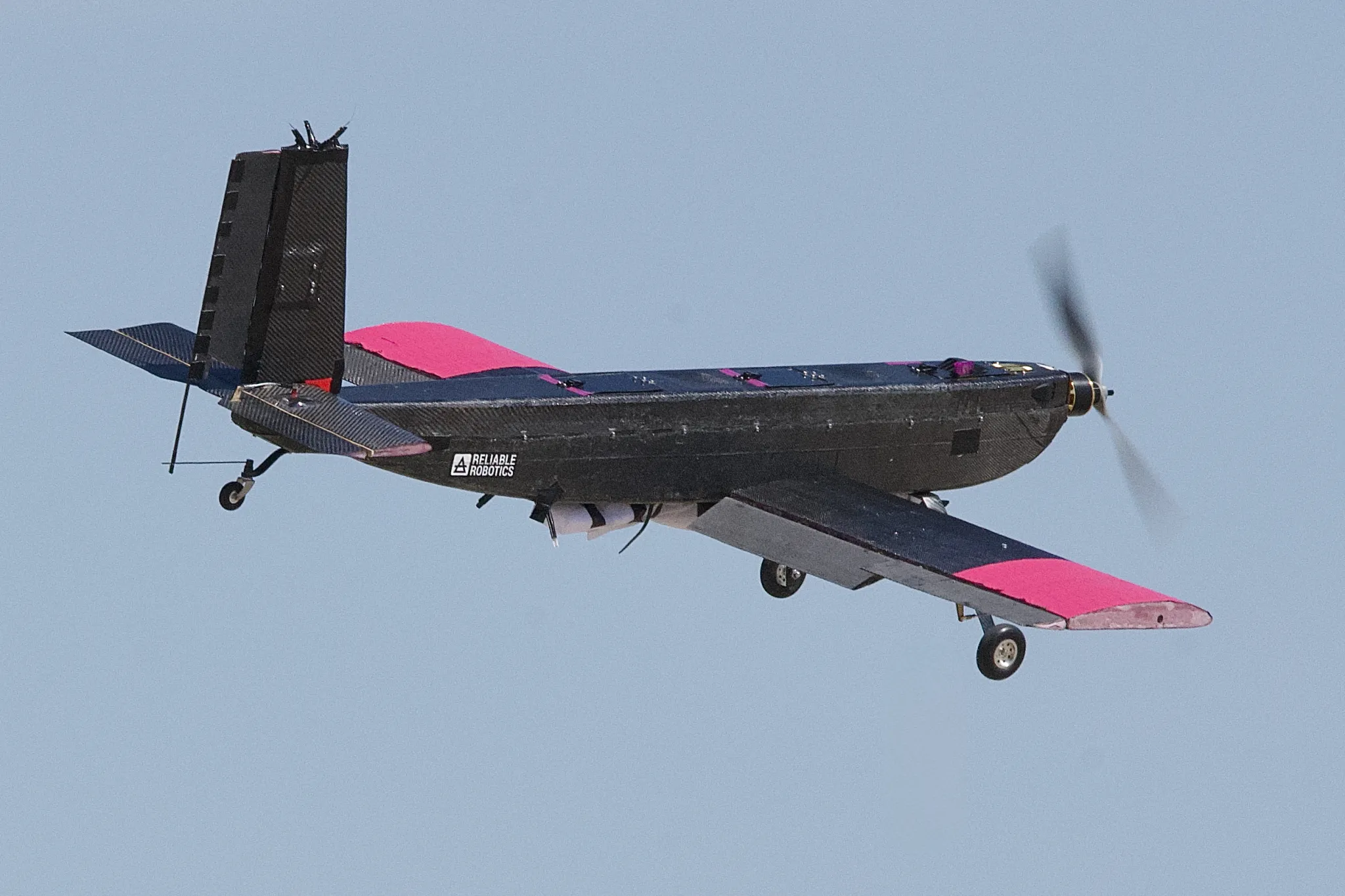
Credit to Missouri S&T/Bob Phelan at phelanb@mst.edu
RC Plane Model 2026 - Peaking Jay!
View Options:
The ultimate competitive edge
In just two years, our team has made tremendous progress. We started small with a foamboard aircraft that weighed only 4 lb, and other teams nicknamed it "the cardboard plane." Despite its simplicity, limited payload, and budget nearly 5–20 times smaller than most teams, we managed to place in the top half of the competition.
Motivated by this success, we aimed higher the following year. We designed and built a 6 ft wingspan wooden aircraft weighing 7 lbs, a major step forward in complexity and ambition. Despite the setbacks when the plane crashed on the first day due to the Arizona heat, we persevered and completed two of the three missions, ultimately finishing in the top third overall.
Now, we aimed even higher. Our team took on the challenge of building a fully carbon composite aircraft — a leap that places us among top-performing teams with decades of experience, much larger memberships, and budgets several times our own. With this effort, we set our goal to finish in the top 20 teams, and worked really hard to finally make it happen!
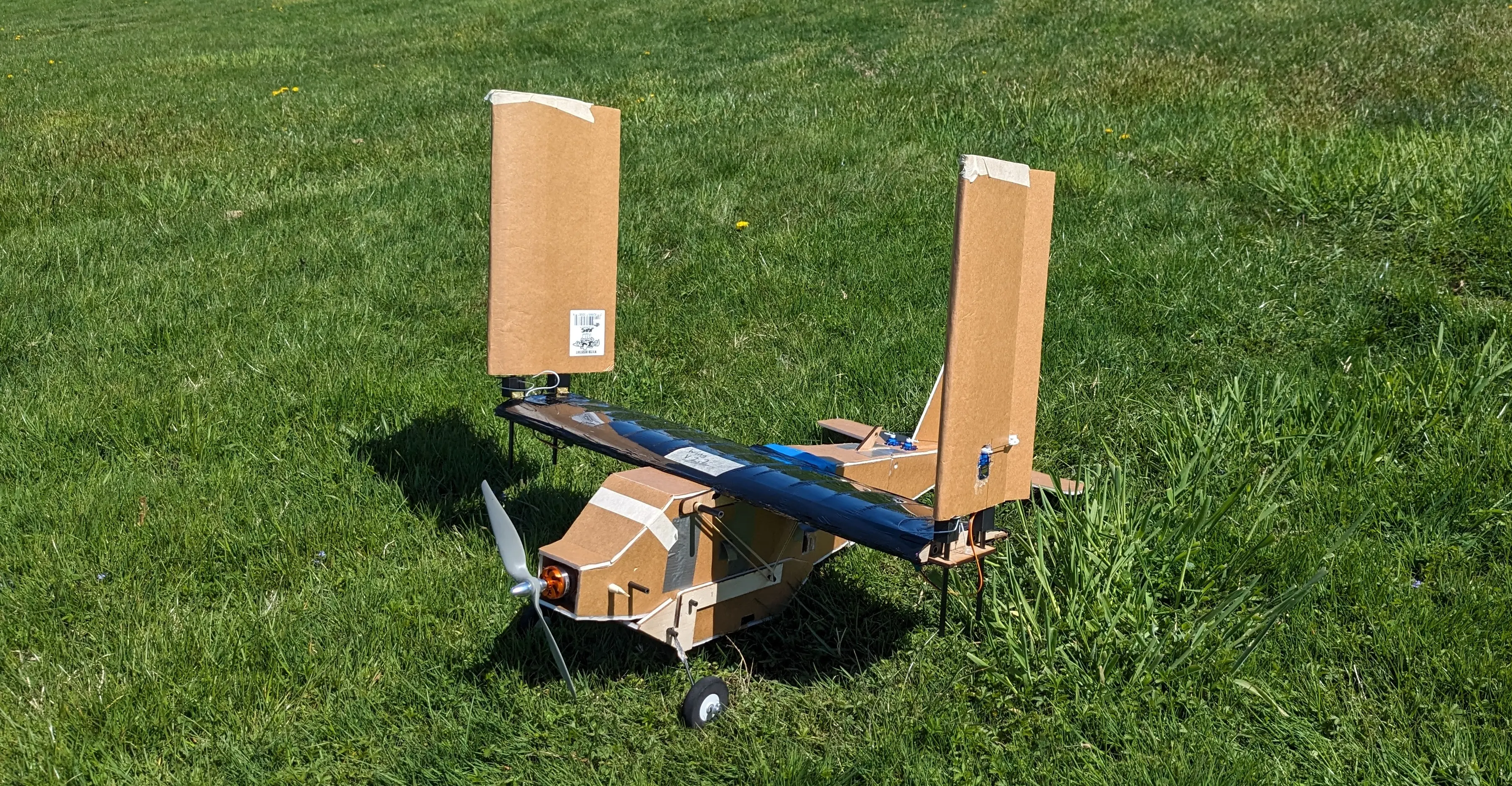
2024 - The Phoenix
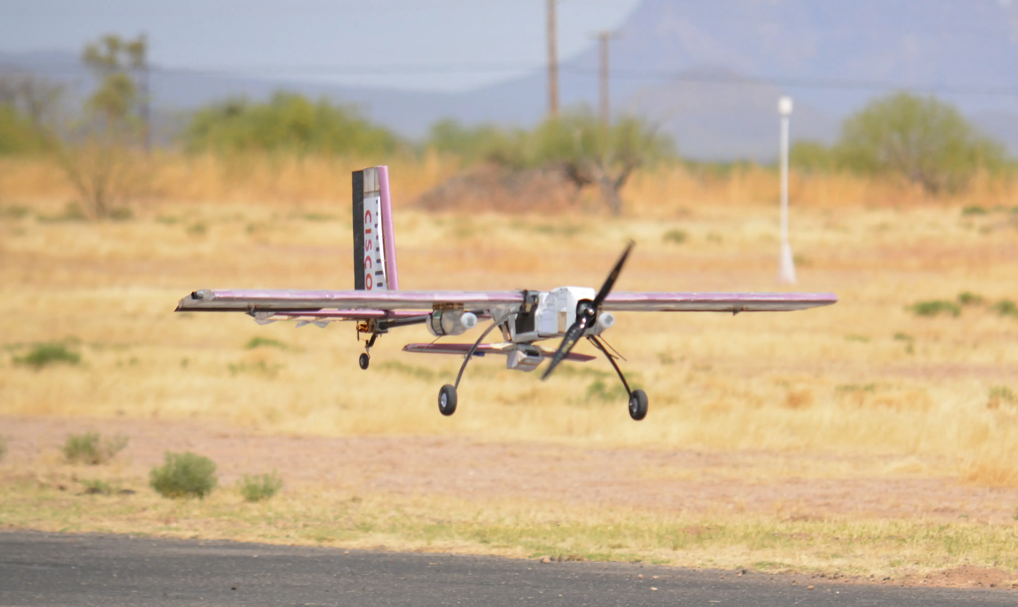
2025 - The Freedom Fighter
Design Specifications
The plane had weighed 14.5 lbs with a top speed of 65 mph. It can carry a large payload in its large carbon fiber fuselage. Additionally, it can tow a large banner (2 x 10 ft) for 5 minutes.
Manufacturing Process Validation
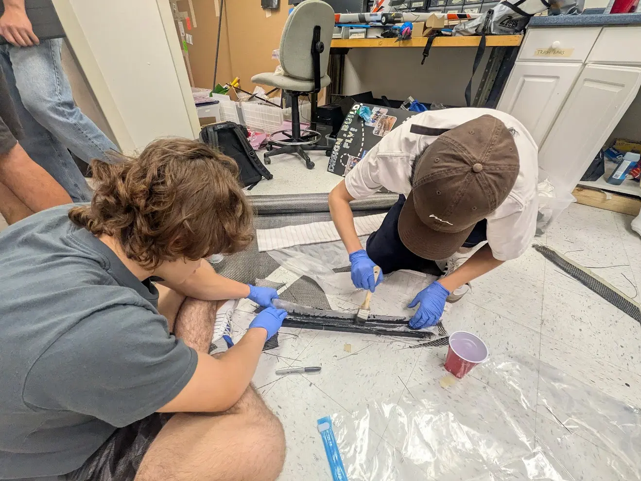
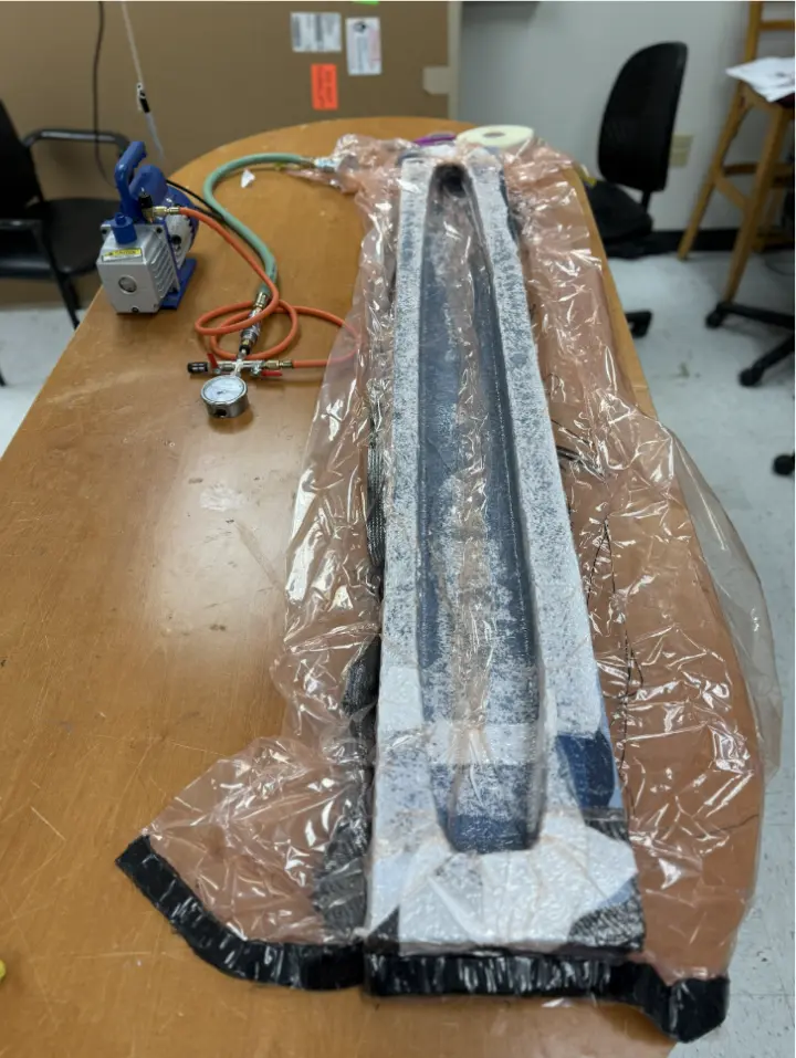
A scaled-down fuselage half was built to validate the manufacturing process and test structural integrity. We set up VCarve to CNC mill two female mold halves out of XPS foam. We then treated them with an epoxy coating to smooth out the surface and applied multiple layers of PVA as mold release agents. We performed a three-layer layup of bidirectional carbon fiber cloth in a 0/90°, ±45°, 0/90° orientation.
Scaled-down prototype
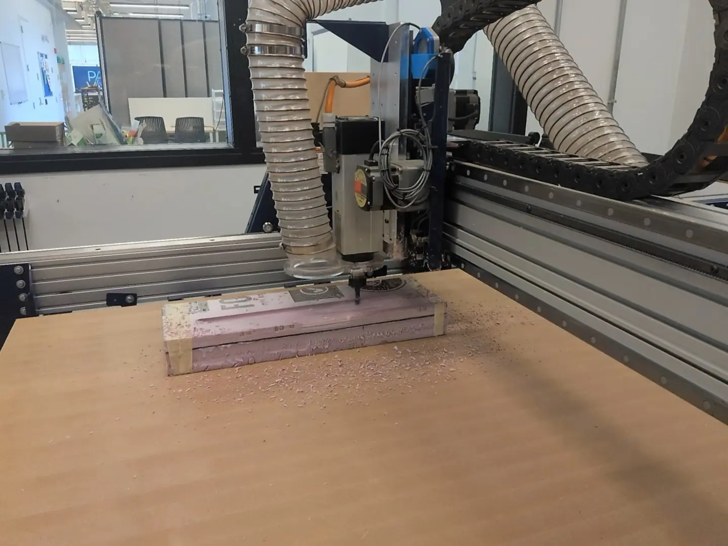
CNC milling the female mold halves
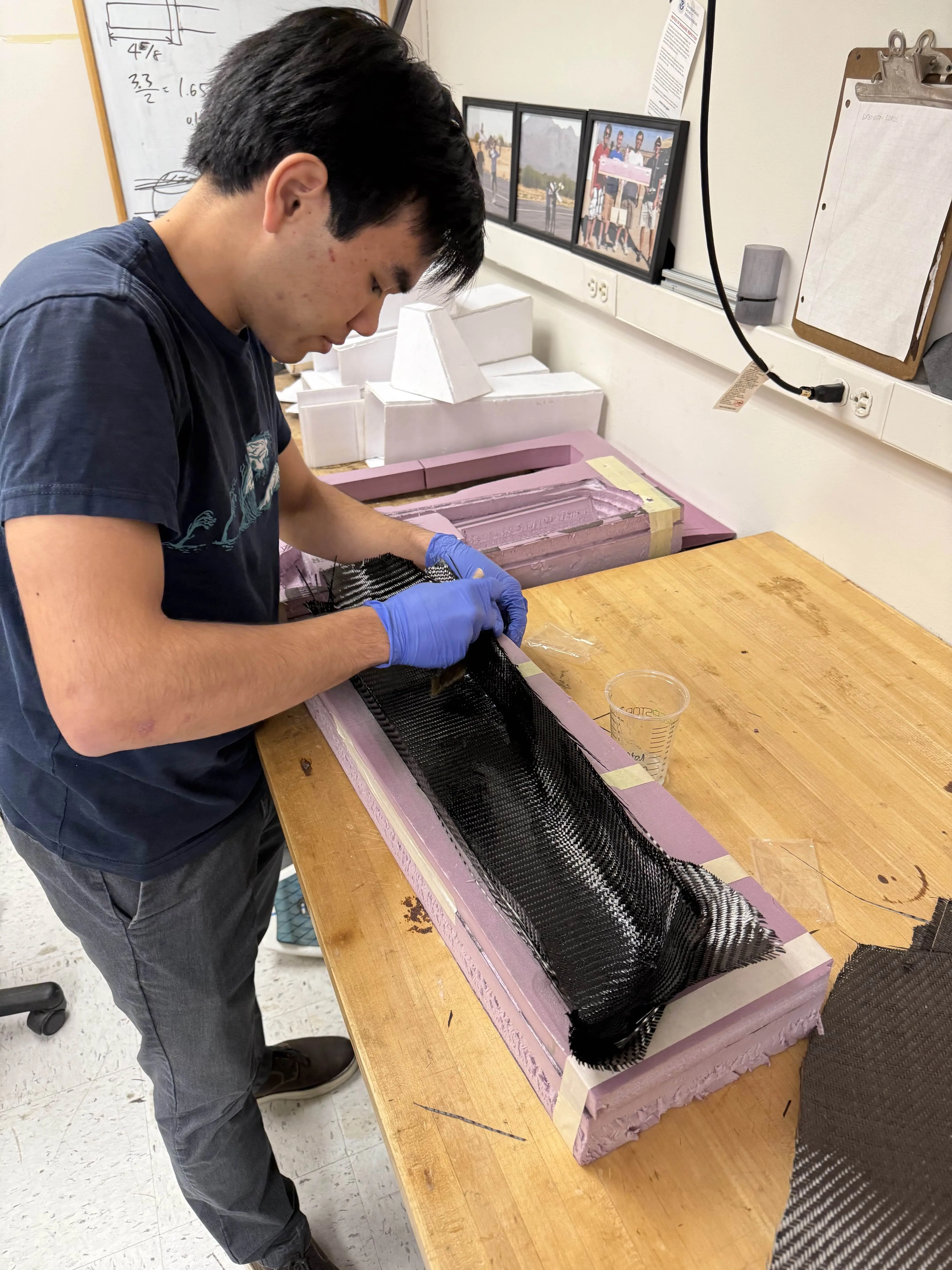
Wet layup process
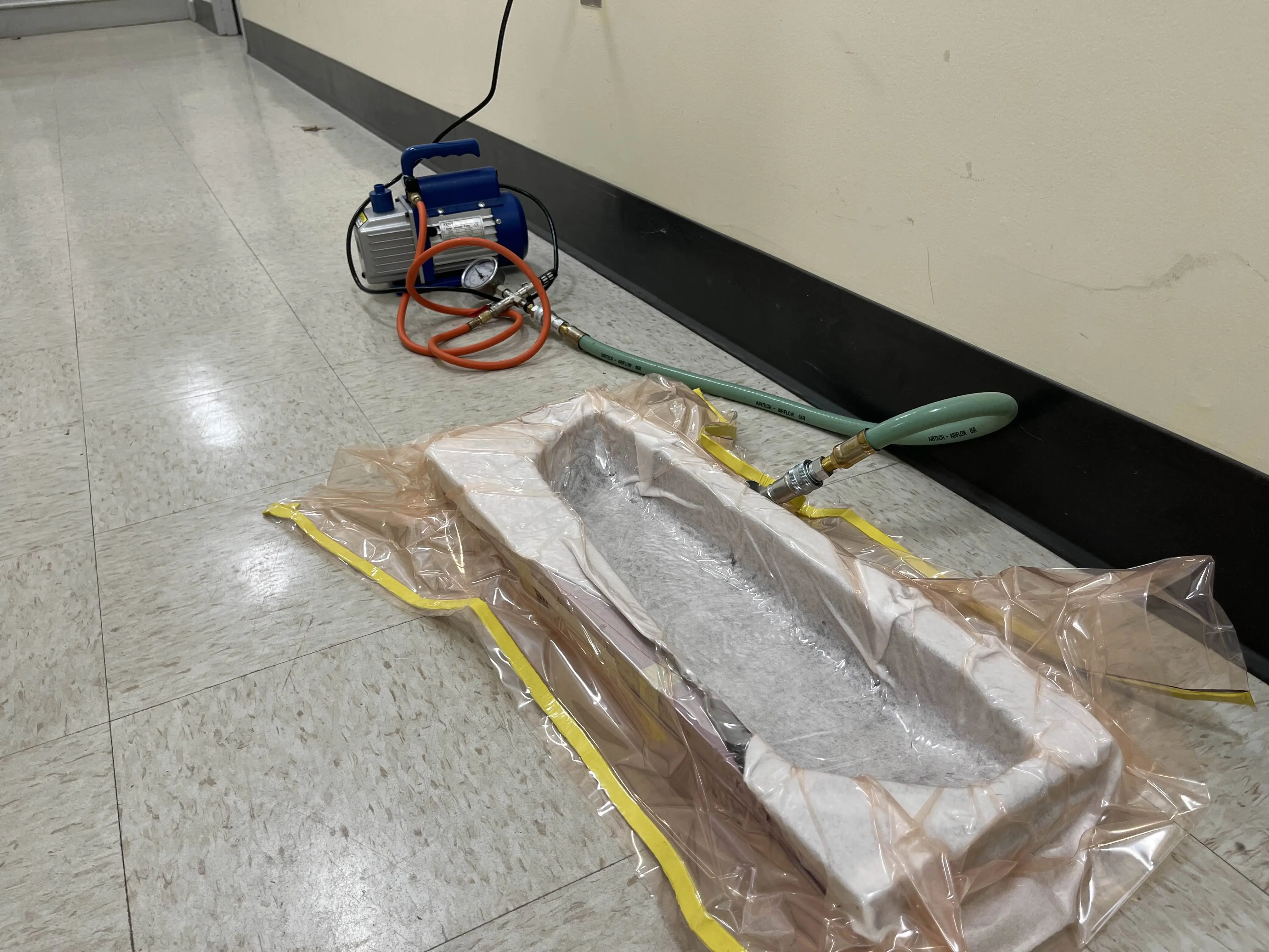
Vacuum bagging technique
Structural Analysis
To validate the wing's structural design, we performed a Finite Element Analysis (FEA) in Abaqus. The model simulated an assembly of an XPS foam core insert, an internal carbon fiber spar, and a skin made from wet layup of two layers of ±45° bidirectional carbon fiber. A distributed lift force (scaled to simulate a 6G maneuver) calculated from aerodynamic parameters, was applied to the cantilevered wing structure. The results confirmed the design's integrity, showing minimal deflection and stress levels safely below material failure points.
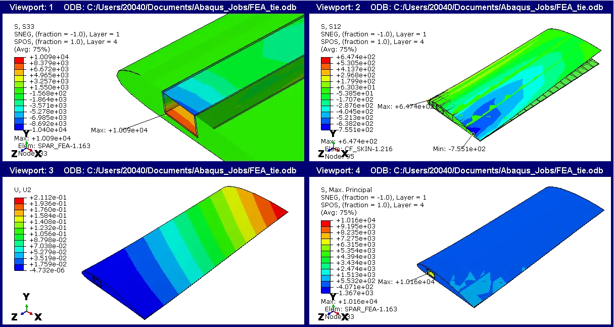
Finite Element Analysis showing stress distribution under 6G load
Custom Manufacturing Tools
The wing is made out of carbon fiber wrapped XPS foam which is hot wire cut using our own custom CNC hot wire cutter. We even developed our own custom g-code generator as there is no open source software which satisfies our need that currently exists.
Using our custom-built CNC hot wire cutter controlled by in-house developed g-code generation software, we built our wing into highly specific airfoil shapes from XPS foam. We then wrapped the shaped foam with carbon fiber to achieve our rigorous structural requirements. Our specialized tools give us an advantage in manufacturing capacity and quality, as no existing tooling has been available for our needs until now.
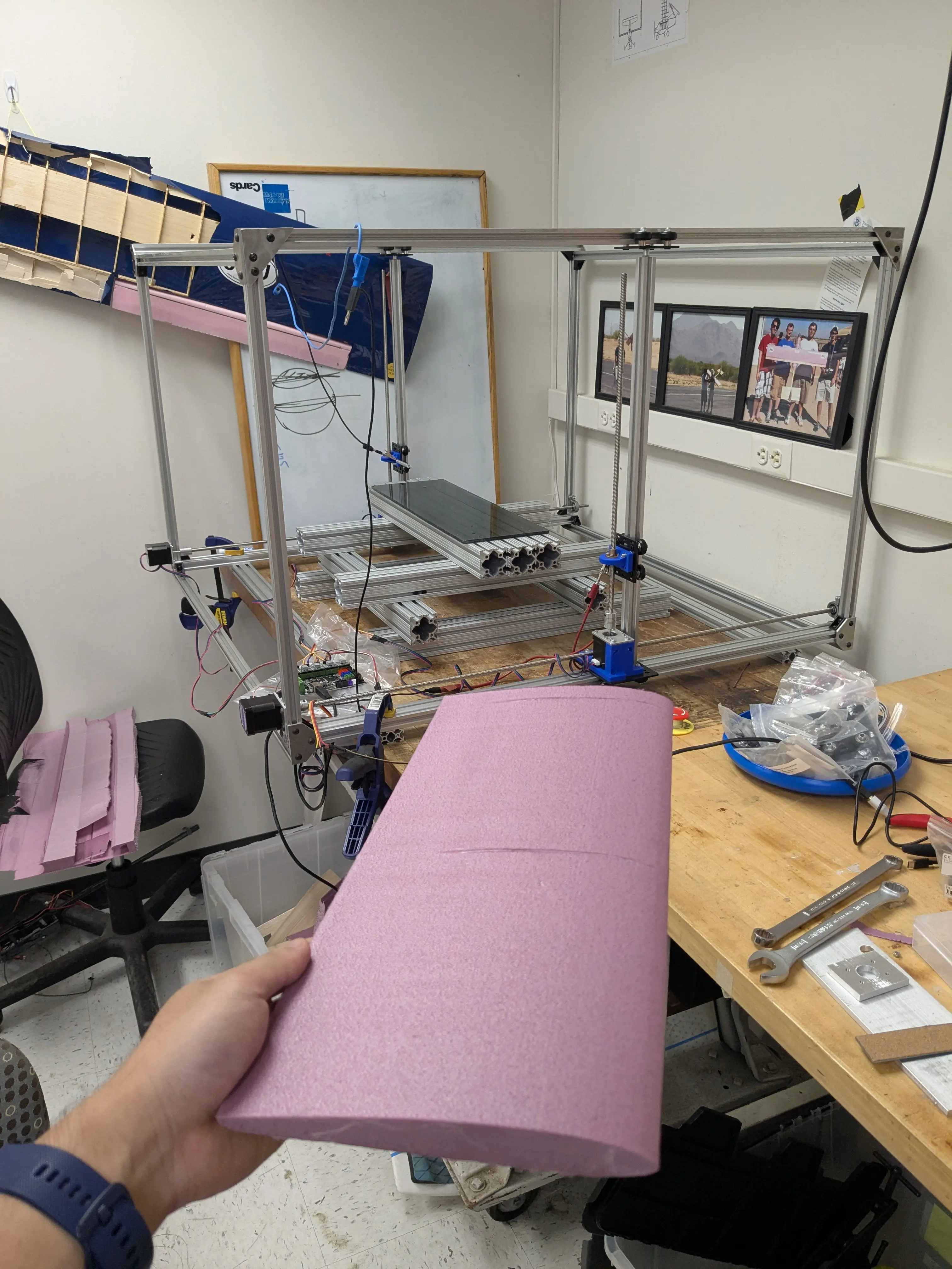
Our custom-built CNC hot wire cutter

In-house developed g-code generator

Final carbon fiber fuselage prototype
Putting all the main components together
Our final plane is a scaled up version of our prototypes. We laid up two halves of the fuselage with carbon fiber and decided to join them together using M3 bolts and nuts.
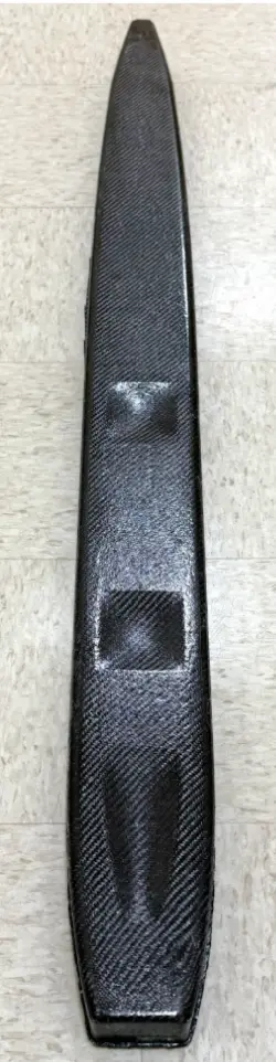
Final laid-up carbon fiber fuselage
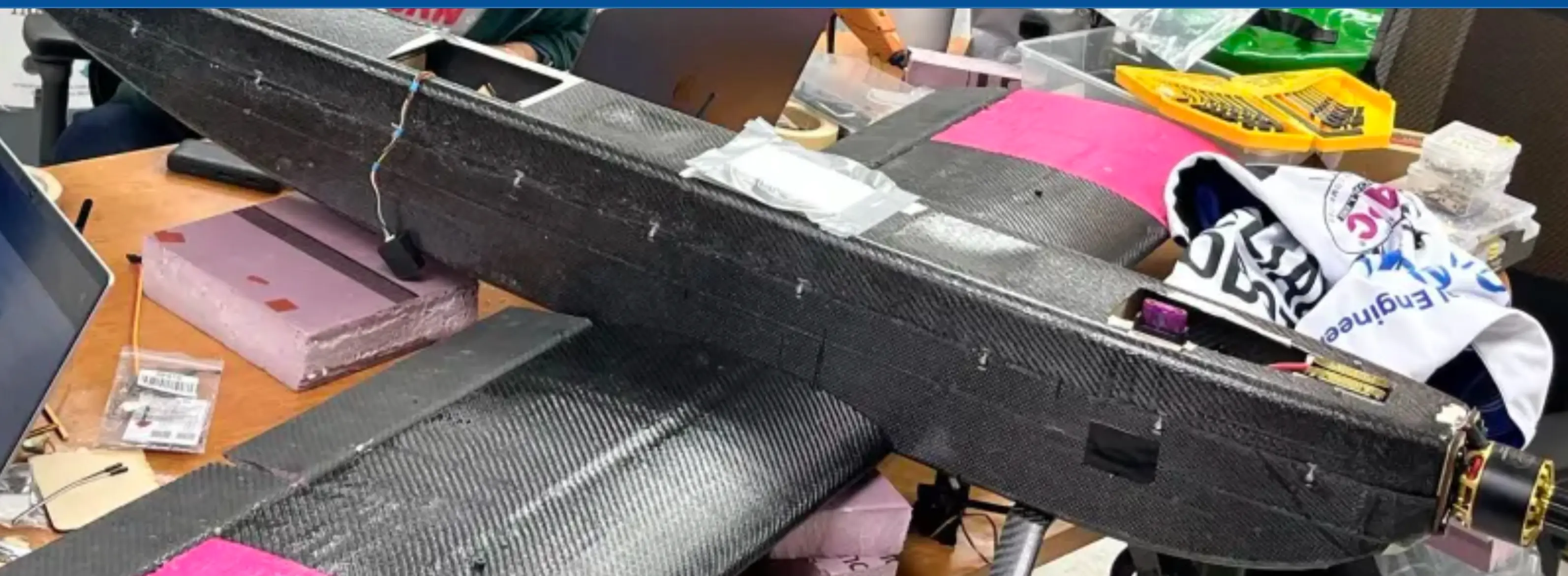
Fuselage halves bolted together with M3 hardware
This year's second mission involved flying the plane with a payload of duck and hockey puck passengers. We installed these passengers using “Duck Burgers” and hockey puck trays. The burgers slid in through the two holes on the top of the fuselage and the trays were inserted at the very front of the plane, directly under the propeller.
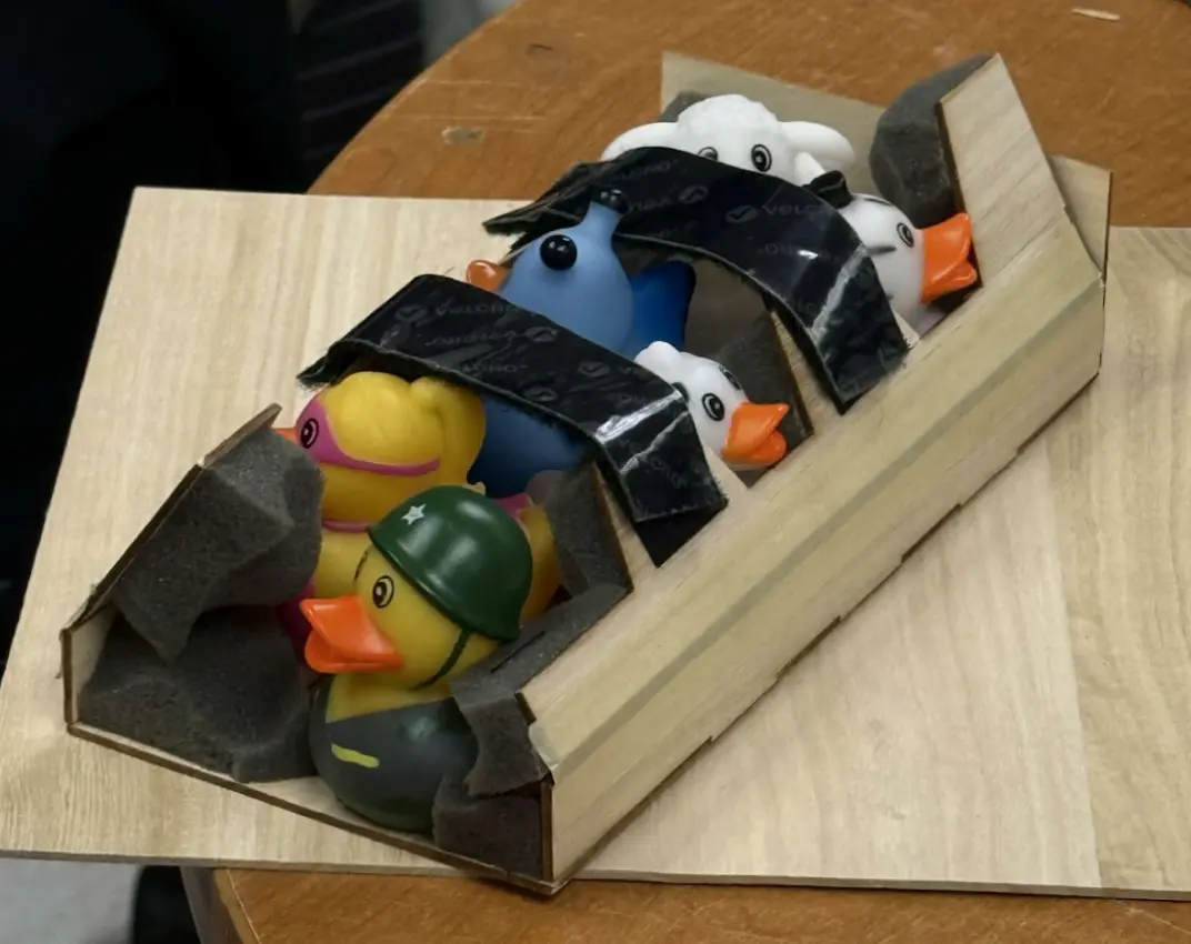
The iconic “Duck Burgers” that secured the ducks inside the plane
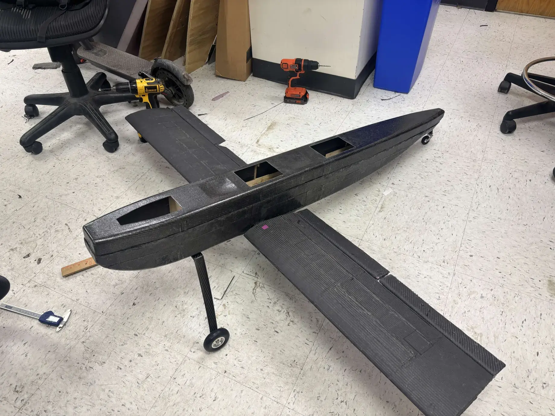
Cuts on the fuselage for payload entry

Our hockey puck tray designed to fit under the burgers
The two laid-up foam wings were joined together using the middle carbon fiber spar: the spar stays fixed inside the fuselage at the approximate location that balances the center of gravity, so that the wings can be removed and re-inserted at any time.
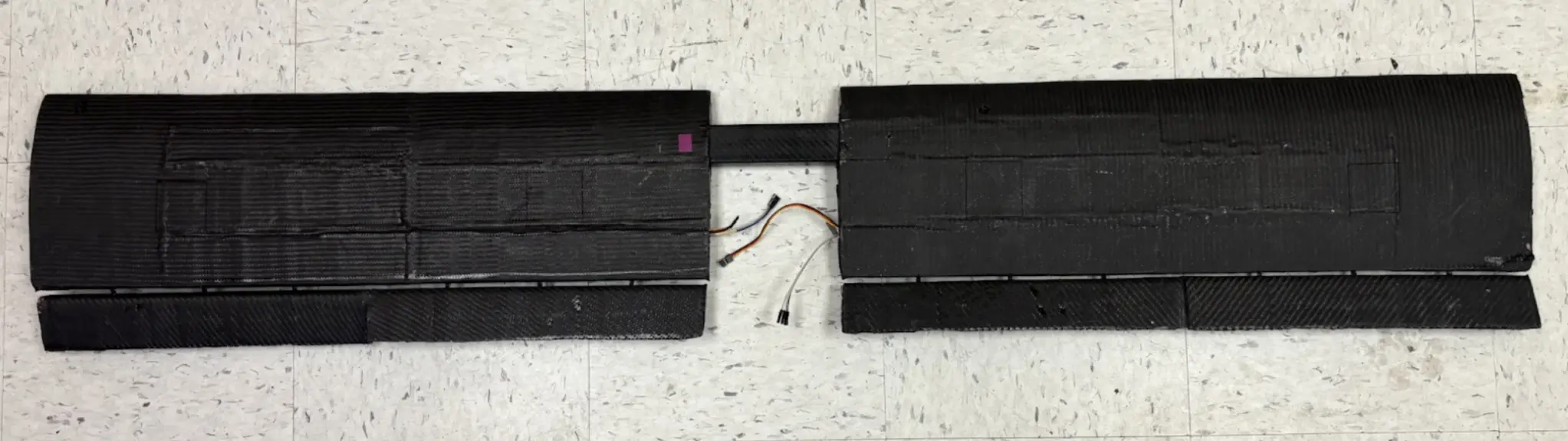
The central carbon fiber spar that joins the wings
The tail is ultimately joined with a laser-cut prism that locks both the horizontal and vertical stabilizers in place.
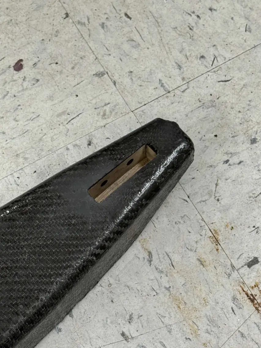
Laser-cut prism tail connector
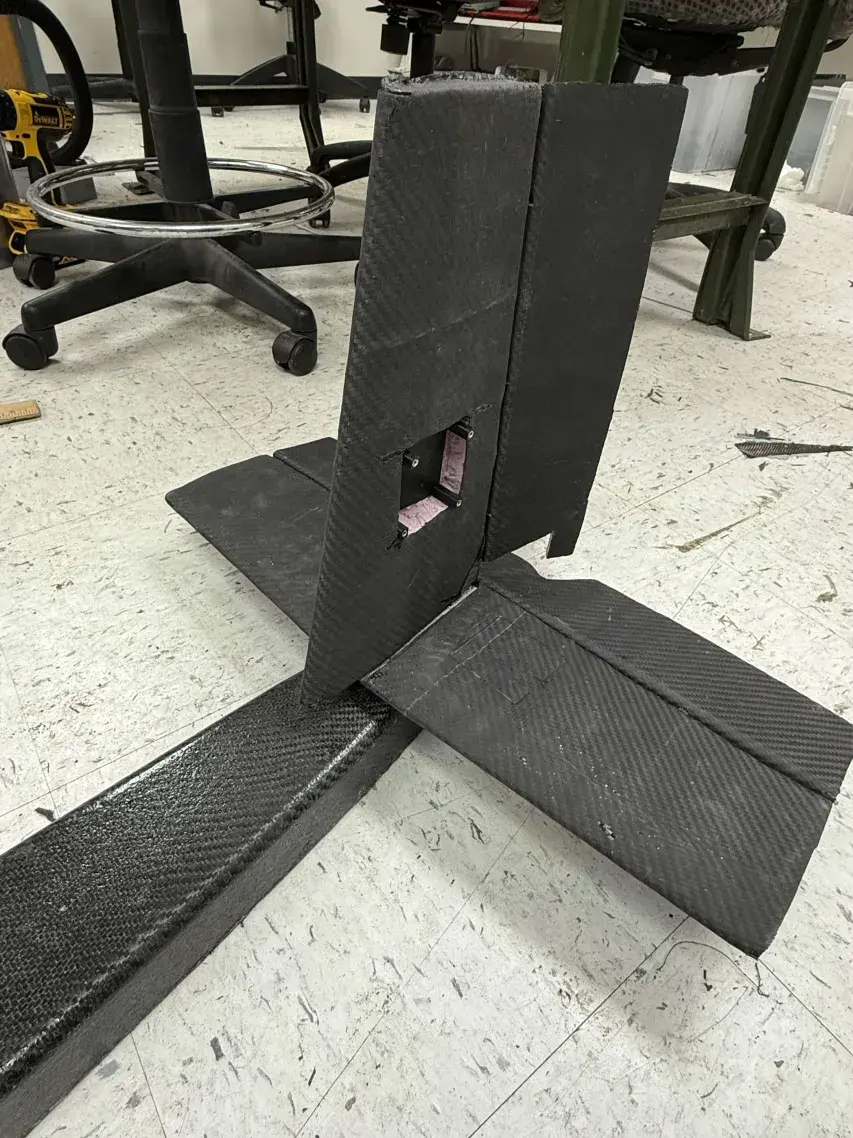
Tail installed with both stabilizers locked in
This year featured a final mission that required us to drop a banner behind our plane, fly it for several minutes, and release it so that it reaches the ground. In order to execute a smooth deployment of the banner, we created a sliding pin mechanism staged inside the plane that controlled the unfurling of zip-tie bands around the banner.
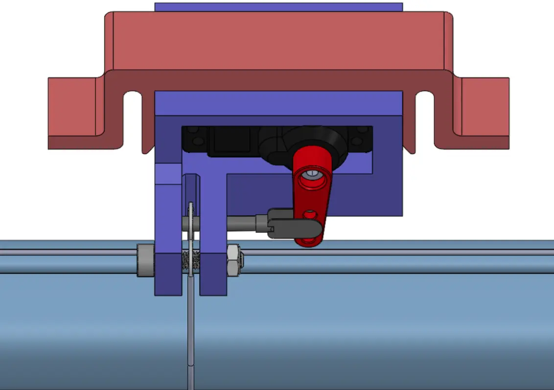
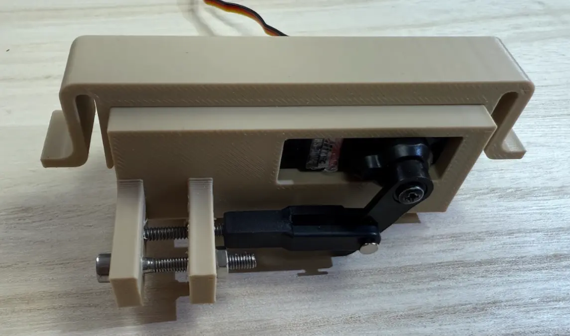
Pin-Sliding Mechanism - 3D Print and CAD
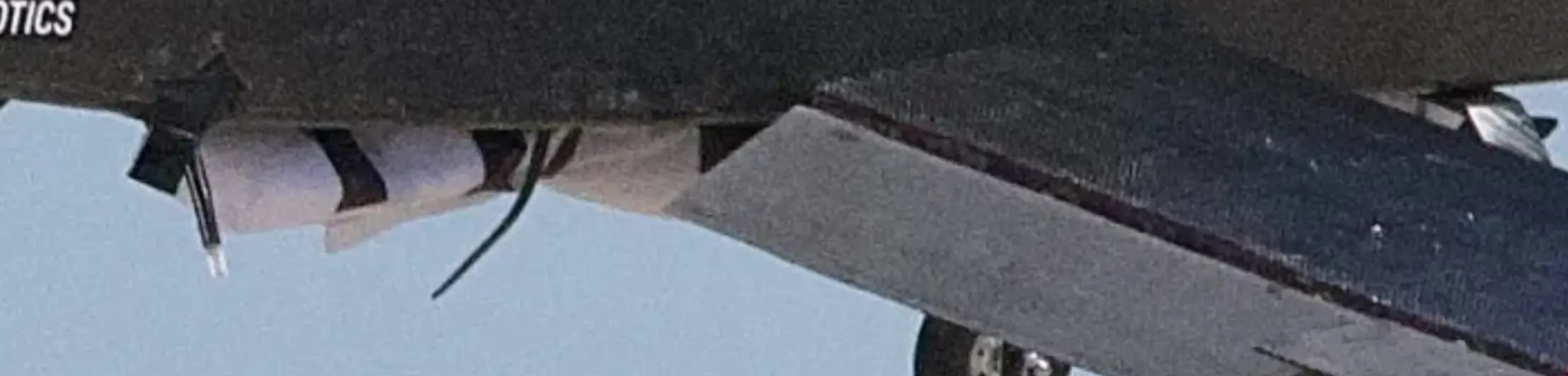
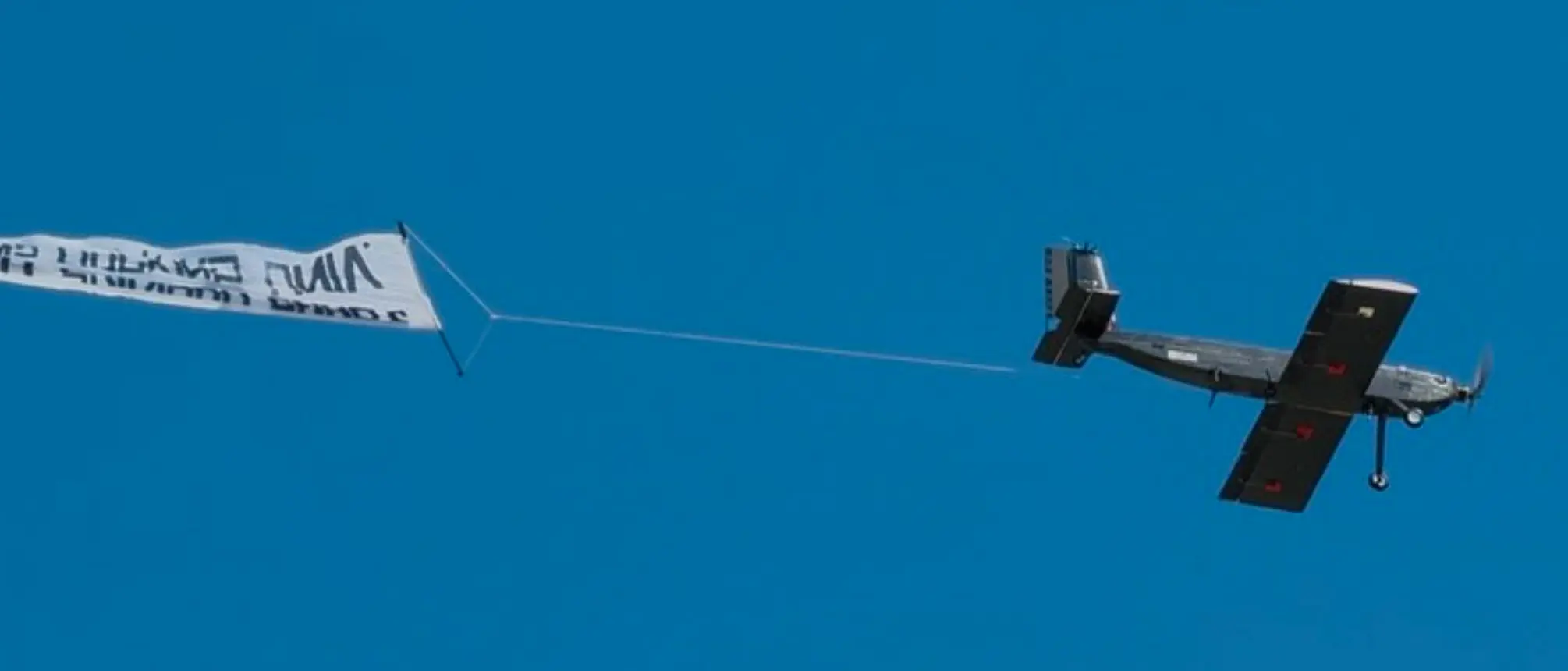
A successful release of the banner, solidifying our top 20 spot
Our 2026 Goal
Finish in the Top 20 Teams
With our fully carbon composite aircraft and innovative manufacturing techniques, we competed with the best teams in the nation and finished in the Top 20 of 175 teams, achieving a lifelong goal for our club! From here, it will only be up: next stop, Top 10!
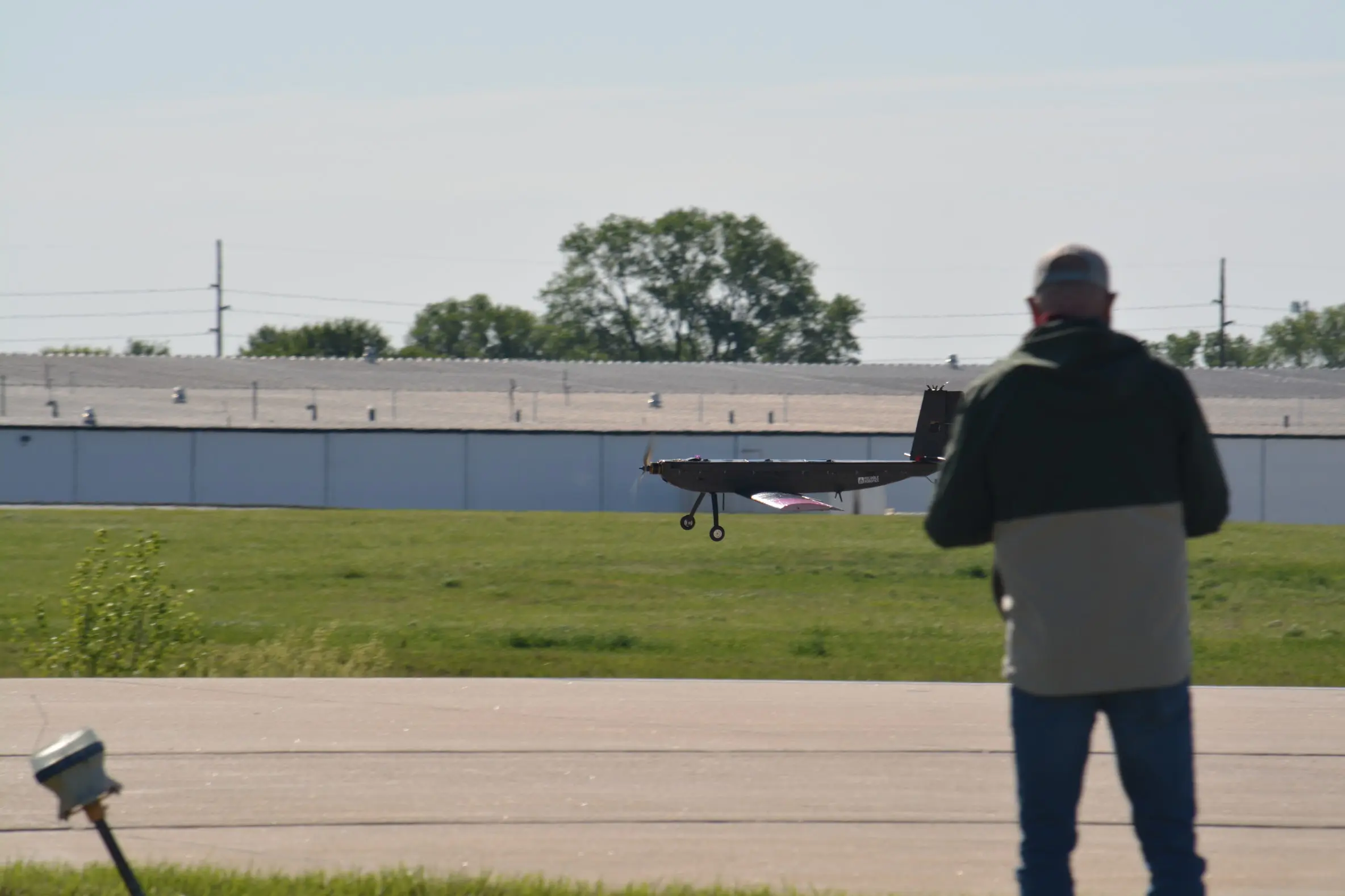
Peaking Jay coming in for a landing